


DIY - How To Install A Whole House RO System
Item List

1. Solenoid Valve - Turns ON/OFF Feed Water Supply when the tank input circuit is open.
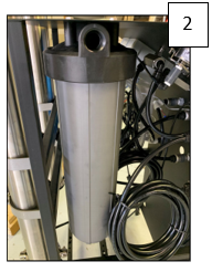
2. (5) Micron Sediment Pre-Filter - Removes Sediment from the Feed Water.
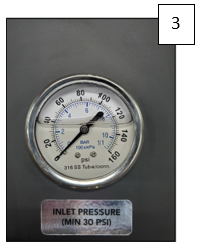
3. Pre-Filter Pressure Gauge - Monitors Feed Water Pressure prior to the Pre-Filters
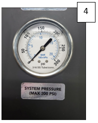
4. Pump Pressure Gauge - Monitors the Membrane/Pump pressure during operation. WARNING! Do not exceed 150 psi.
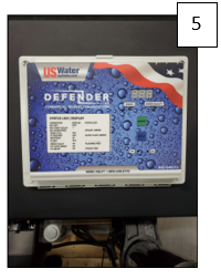
5. Computer Control - The US100 Controls ON/OFF Function as well as Fail Safe Switches.
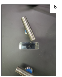
6. Recycle/Recirculation Valve - Controls the amount of Concentrate Water that is fed back to the Membranes for Recycle.
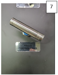
7. Concentrate/Waste Vale - Controls the amount of Concentrate Water going to the drain for waste.
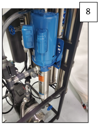
8. Pump and Motor - Boosts the Feed Water Pressure to the Membranes
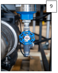
9. Throttle Valve - Adjust the Boost Pressure to the Membranes. WARNING! Do not exceed 150 psi.
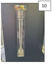
10. Permeate/Product Flow Meter - Monitors the amount of Permeate Water going to the storage or distribution systems.
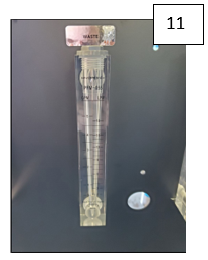
11. Concentrate Flow Meter - Monitors the amount of Concentrate Water going to drain.
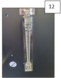
12. Recycle/Recirculation Flow Meter - Monitors the amount of Concentrate Water being recycled to the Membranes.
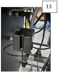
13. Low-Pressure Switch - Shuts the system down as a fail safe in a Low Feed Water Pressure Condition. This pressure switch is in the RO Controller.
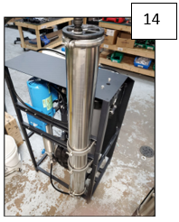
14. Membrane Pressure Vessels - Holds the Membranes.
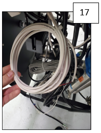
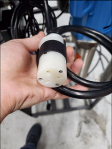
15. Power Supply Cord.
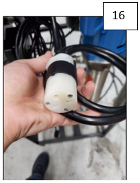
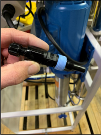
16. Injection Pump Electrical Connection.
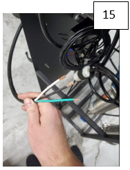
17. Tank Level or Pressure Shutoff and Pre-treatment Lockout Connections. WARNING! This input is a NO VOLTAGE dry contact. DO NOT apply voltage input!
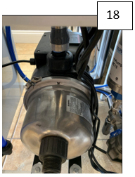
18. Re-pressurization Pump - Pressurizes the water from the Storage Tank to supply the plumbing distribution system.
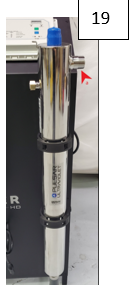
19. UV Light - Used to destroy bacteria that may be in the water prior to the plumbing system. (Final Connection to Plumbing Distribution System marked as a).
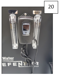
20. UV Controller - Monitors the UV light performance and bulb life.
Tools Needed: two channel locks, Teflon Tape
Installing Your RO System
System Connections, Requirements and Guidelines
1. PLUMBING
The high-pressure pumps used on the defender systems require a continuous flow of water with a minimum feed pressure of 35 psi, and water temperature not exceeding 105°F while the system is running.
2. FEED WATER CONNECTION
- Locate the 1 FNPT inlet connection on the sediment filter housing.
- Attach the inlet piping to the 1 FNPT filter housing inlet.
- NOTE: FEED LINE MUST BE MINIMUM 3/4
3. PERMEATE (PRODUCT WATER) CONNECTION
- Locate the 1/2 tubing labeled permeate and attach to the bulkhead in the top of the storage tank. Ensure that the permeate water can flow freely with no back pressure. Back pressure can cause irreversible damage to the membrane elements.
- NOTE: ALL PERMEATE PLUMBING SHOULD BE DONE WITH PLASTIC OR STAINLESS STEEL. SOFT METALS WILL LEACH INTO THE WATER STREAM. CPVC, PVC, PEX AND STAINLESS STEEL ARE THE MOST COMMONLY USED MATERIALS
- CAUTION: THE PH OF THE REVERSE OSMOSIS PERMEATE WATER WILL TYPICALLY BE 1-2 POINTS LOWER THAN THE FEED WATER PH. A LOW PH CAN BE VERY AGGRESSIVE TO SOME PLUMBING MATERIALS SUCH AS COPPER PIPING
4. CONCENTRATE (WASTE WATER) CONNECTION
- Locate the 1/2 tubing labeled concentrate and attach/convey to a drain. Run the concentrate line to an open drain in a free and unrestricted manner (no back pressure). It is recommended that an air gap be maintained on the drain line to prevent possible bacterial contamination.
- CAUTION: ANY RESTRICTIONS OR BLOCKAGES IN THE DRAIN LINE CAN CAUSE BACK PRESSURE, WHICH WILL INCREASE THE SYSTEMS OPERATING PRESSURE. THIS CAN RESULT IN DAMAGE TO THE SYSTEMS MEMBRANES AND COMPNENTS.
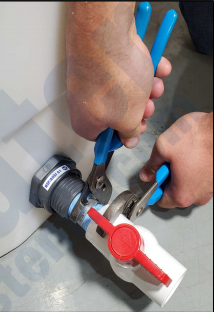
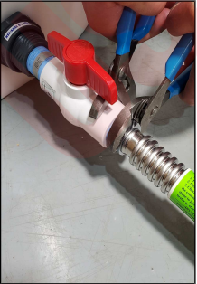
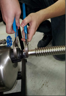
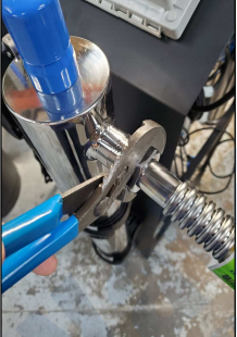
5. RE-PRESSURIZATION PUMP CONNECTION
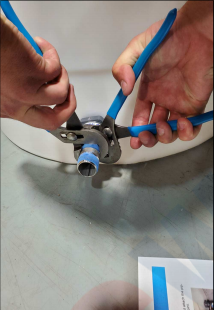
Apply Teflon tape to the supplied 1 stainless steel nipple and install into the bulkhead located at the bottom of the atmospheric storage tank. Tighten using two pairs of channel locks. Then install the supplied ball valve using the same method. Locate the 1 male threated connection on the re-pressurization pump and attach the piping from the bottom of the storage tank. Do not turn the pump on at this point.
6. PLUMBING DISTRIBUTION SYSTEM CONNECTION
- Locate the 1 male threaded connection on the UV light chamber and connect piping to the plumbing distribution system.
Electrical Connections
1. Main System Power
The main power on the Defender system is available in 220 volt, 60 Hertz, 1 Phase. Each Defender system is equipped with a 5 foot electrical cord. This can be hardwired in a disconnect box or an outlet box can be installed that matches the cord end for the respective voltage. This should be powered by an isolated 20 amp breaker.
2. Re-Pressurization Pump
The re-pressurization pump requires 110 Volt, 60 Hertz, 1 Phase. This should be connected to a constantly energized 110 Volt outlet. The pump is equipped with a standard 110 Volt cord end.
3. UV Light Controller
The UV Light Controller requires 110 Volt, 60 Hertz, 1 Phase. This should be connected to a constantly energized 110 Volt outlet.
IMPORTANT NOTICES
WARNING: To prevent possible circuit overload, it is best to run isolated circuits to supply the RO system and the UV Light and Re-pressurization pump
The RO system should have a 20 Amp Breaker. The UV Light and Re-pressurization pump can share a 20 Amp Breaker.
NOTE: It is recommended that a licensed electrician wire the system in accordance with the local and national electrical codes.
WARNING: To reduce the risk of electrical shock, the incoming power supply must include a protective earth ground.
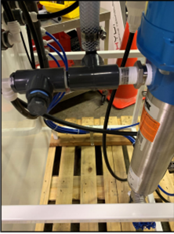
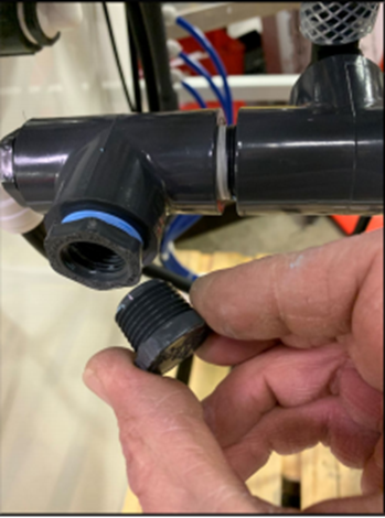
NOTE: If the anti-scalant option was purchased, the injection check valve that comes with the anti-scalant pump should be put in the injection tee on the booster pump inlet plumbing. There is a 1/2 plug that must be removed and the injection check vale can be installed.
BE SURE to Teflon tape the injection check valve threads before installing it in the tee fitting.
Pre-Filtration
The Defender systems do not include pre-filtration. It is VERY important to have pre-filtration before the RO system to ensure longevity and that damage will not occur to the unit. A water test of the feed is used to determine the proper pre-treatment equipment. Contact US Water Systems for help determining what pre-treatment equipment is required.
NOTE: THE SYSTEM MUST BE OPERATED ON FILTERED WATER ONLY. 99.9% OF ALL RO APPLICATIONS REQUIRE SOME FORM OF PRE-TREATMENT. SYSTEMS OPERATED USING UNTREATED WATER WILL HAVE PREMATURE MEMBRANE FAILURES. MEMBRANE FAILURES DUE TO IMPROPER PRE-TREATMENT ARE NOT COVERED UNDER WARRANTY.
Pump
The pump type used on the Defender systems is a multi-stage centrifugal carbon steel pump.
- The pump must NEVER be run dry. Operating the pump without sufficient feed water will damage the pump.
- ALWAYS feed the pump with filtered water. The pump is susceptible to damage from sediment and debris.
NOTE: THE FEED WATER PRESSURE MUST NOT FALL BELOW 30 PSI WHILE THE SYSTEM IS RUNNING. THE SYSTEM WILL SHUTDOWN FOR A LOW-PRESSURE FAULT IF A PRESSURE > 30 PSI CAN NOT BE MAINTAINED. DO NOT ATTEMPT TO ADJUST THE PRESSURE SWITCH. THE PORPER FIX FOR THIS PROBLEM IS TO INCREASE THE FEED PRESSURE WITH A BOOSTER SYSTEM.
Membranes
The Defender reverse osmosis system comes pre-loaded with Thin Film Composite membranes, unless otherwise specified. General membrane element performance characteristics are listed on the next page.
UV Light Sleeve and Bulb
The Defender reverse osmosis systems UV light will not have the Quartz sleeve and bulb installed. This must be done on site. To install the Quarts sleeve and UV lamp, please use the supplied UV light manual for proper installation and startup.
- IMPORTANT! Make sure the quartz sleeve is installed properly and make sure there are no leaks before installing the bulb and powering the UV light.
- BE SURE to install the UV lamp string in the quartz sleeve prior to installing the bulb
Tank Level and Pre-Treatment Lockout Wiring
The Defender system is equipped with two switch closure circuits that control the RO system ON/OFF function. This is a no voltage switch closure circuit (dry contact).
Tank Level Input
There is a switch closure circuit used to turn some RO systems on and off when an atmospheric tank float is installed. The float switch wires as follows:
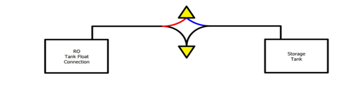
- The wires above show color coatings. However, the colors do not matter. There is no voltage to these wires. They just need to be wired in a loop that can open or close when necessary. BE SURE to use the blue and black wired only on the float.
- IMPORTANT! Do not apply voltage to the tank level input circuit. This will damage the RO system.
Pre-Treatment Lockout Wiring
These outputs can be wired into the rank Pre-treatment Lockout Inputs. This will shut the RO module down while the backwashing filter or softener is in regeneration/ backwash. This option is utilized to ensure there is no untreated water fed to the RO system when a pre-treatment device is in regeneration/backwash. The pre-treatment output switches will be wired as follows:
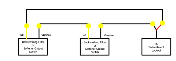
- The wire above show color coatings. However, the colors do not matter. There is no voltage to these wires. They just need to be wired in a loop that can open or close when necessary. BE SURE to use the Normally Closed (circuit opens when regeneration/backwash starts and closes at the end of all cycles) wires only on the Backwashing Filter or Softener output switch.
- IMPORTANT! Do not apply voltage to the Pre-treatment lockout connection circuit. This will damage the RO system. BE SURE the pre-treatment output switch on the backwashing filter or softener DOES NOT supply power.
Anti-Scalant Filling and Settings
If ant-scalant is used in lieu of a water softener to control hardness, the dose and mix is determined using the feed water analysis, the chemical pump specifications and the RO system operating parameters. The table below can be used in 90% of the applications. However, in some rare cases, the US Water Systems Specialist will make it known. Use the following procedure:
- Fill the tank with 5 gallons of clean water (preferably RO water). Add specified oz of the Hyper-Guard Plus 7000 anti-scalant solution for each gallon of water to the tank using the table provided.
- Cut the smooth portion of the injection check valve off, up to the male threads. This is to ensure the outlet does not bottom out and restrict flow of the solution.
- Install the injection check valve in the chemical injection port on the RO system after the sediment filter. This should be labeled with a pipe plug installed.
- Plug the chemical injection pump into the chemical injection pump female cord labeled Dosing Pump on the RO system. This cord is energized when the RO system is operating.
- Make sure the toggle switch on the injection pump is in the ON position.

System Start-Up
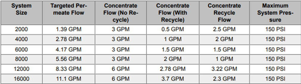
Adjusting the RO System Flow Rates
- Be sure the pre-treatment systems have been flushed and put in service. If anti-scalant is being used, be sure to confirm the does and mis of the solution with the rep before starting the system.
- If possible, remove the pre-filter and fill it with water. This will remove the majority of the air in the system.
- Make sure the water supply is turned on and that you have a minimum of 30 PSI to the system. The optional pressure would be 60 psi. NOTE: SYSTEM RUNNING PRESSURE CANNOT FALL BELOW 30 PSI.
- Open concentrate valve completely by turning it counterclockwise. Close the concentrate recycle valve (if applicable) completely by turning it clockwise.
- Turn the RO system on.
- Let the system run for 5-10 minutes to flush the remaining air out of the filters and membranes. NOTE: The system may nee to be shut off and turned back on several times to flush the air out and for the system to continue to run. This may be increased if the sediment filter is not filled with water first.
- Check the running inlet pressure. The pressure should be between 40-60 PSI (30 PSI minimum) during operation to ensure the system will not shut down due to a low pressure fault.
- Adjust the system to the designed flow rates without exceeding 150 PSI on the pump/membrane pressure gauge. This adjustment is system and site specific. The concentrate valve, concentrate recycle valve, and the throttle valve on the pump will need to be balanced so the RO meets the designed flow rates for each stream without exceeding 150 PSI on the System Pressure Gauge.
1 comment